Composite Application Validation System (CAVS) is part of the Application Integration Architecture Foundation Pack and with CAVS you can test your SOA Composites like SOAPUI or the SOA Test Suite. SOAPUI can test your composite services and it can mock an other service but you need to redeploy some composites to override the endpoints ( so it uses the mocked services endpoints ). The SOA Test Suite is also Ok but is focused to 1 composite. An AIA Process usually contains many composites. So for AIA you need a Test framework who can send a request and can simulate some Composite adapter references services and without redeploying any composites. CAVS can do this for you.
In every Application Business Connector Service (ABCS) of your AIA Process you can do a redirect to a simulator. In this blogpost I will show you how this works. I start with a simple test of a service, grouping some tests together, simulate a service and combine tests and simulators with CAVS routing.
First we start with a simple Test of a SOA Composite Service.
Go the AIA Homepage and press the go button in the Composite Application Validation System window.
Test definition
In the definitions tab you can see your already defined tests and simulators. Press the Create Test button.
Provide the details. Add the endpoint of the Service you want to test. With Get Operations you can select an operation. To generate a test message press Get Messages.
Add a request between the cavs:CAVSRequestInput_1 element, you can add more then one request. Add a cavs:CAVSRequestInput_2 element etc.
Provide the matching Response messages in the matching cavs:CAVSResponseOutput_X element.
Important press Generate Xpath so it will generate the validation rules for this test.
Provide all the namespaces you use in this test.
When you pressed Generate Xpath on the response window you can see all the validations rules ( these based on the response message) You can add your own.
You are ready to test your service. Select your test and press Execute.
In the instance tab you can see the result.
Group Definition
With a Group Definition you can combine test definitions to one group test
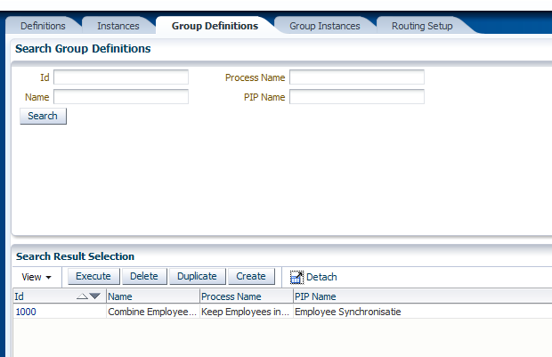
Assign some test defintions to this group definition.
You can execute the group definition and look at the instances tab for the results.
Simulation Definition
With a simulation you can for example emulate an reference adapter service of a Provider ABCS. To make an simulator go to the definition tab and press the create simulator button. Provide the values
Add the expected request messages you can receive in this simulator, start with cavs:CAVSRequestInput_1, you can add more expected messages use the right cavs:CAVSRequestInput_X element. Press Generate Xpath for the validation entries.
Provide the response messages of this simulator.
Provide the namespaces.
When you pressed Generate Xpath on the request messages then you will find some Xpath validation entries. Very important to provide the node key on every request message so CAVS can detect the right request message and give back the matching response. In my case 122 is the unique identifier.
The simulator part is finished, now you can assign this simulator to a ABCS.
When you create an ABCS with the JDeveloper AIA service constructor, it will create a AIAServiceConfigurationProperties.xml file. This file contains the endpoint url's and if it needs to route the reference to a CAVS simulator.
The AIA deployment framework will add this AIAServiceConfigurationProperties to the AIAConfigurationProperties.xml file ( located in AIA_Home\aia_instances\AIA_Instance\AIAMetaData\config )
and also located in the MDS in the config folder
To route every request to a simulator you need to go the AIA homepage and press the Go button of the setup window. Go the AIA Configuration Tab.
Press add on the ABCS you want to add a simulator to it and select a simulator
Enable the Route To CAVS option
When you open the AIAConfigurationProperties.xml you can see that the ABCS properties are changed
The changed ABCS entry.
The last part is to combine Testing and Simulation by making an Routing Setup.
Routing Setup
In a Routing Setup you can add particular simulation to one or more ABCS and use this in a test definition.
Create a Routing Setup
Add a simulator to the ABCS.
And open the Test definition and lookup the Routing Setup
This will set the simulator on the ABCS's before the test is executed.
That's all and hope this gives you a quickstart in the AIA CAVS tool.
Saturday, March 19, 2011
Sunday, March 6, 2011
Set the Initial Focus on a component in a Page or a Fragment
In ADF 11g you can use the initialFocusId property of the af:document component to set the input focus on a UIComponent. On the UIComponent you need to set id property and set the clientComponent property to true. And use this id in the initialFocusId property of the af:document component which is only located in a ADF Page. This is not so hard to do, but sometimes it can be tricky to find the id of a component when you use regions ( Bounded Task Flows ). To solve this you can use the developer tool of Google Chrome or the Firebug plugin of Mozilla FireFox. Select the UIComponent and take a look at this id, you can remove the ::content part.
To set the focus on an UIComponent in a dynamic Region can be hard because this id of the component is not always the same. It depends which Task Flow you open first ( sometimes it is region1:1:input1 or region1:2:input1 ) . And the second problem you have that you need to use some javascript to set the focus.
The solution is to lookup the region UIComponent and try to find the UIComponent from there, get the clientId and use this value.
Here are some screenshot of the possible scenarios.
Set the focus on the Label 2 item, this is in the ADF page.
Same page but now I set the focus on the DepartmentName in the Department Dynamic Region.
New page but with a static Employee Region.
Example page with the af:document and initialFocusId property set on a managed bean
The managed bean which controls the focus
Here is the example workspace
Thursday, March 3, 2011
Setting a virtual IP on a specific Network interface with WebLogic 10.3.4 PS3
If you want High Availability in WebLogic you need to enable the WebLogic server migration, configure the nodemanager, use a virtual / floating IP in your managed servers and channels. For more information see my nodemanager blogpost.
Before PS3 you could only add a virtual IP on a pre-defined network interface and subnet mask, these fixed values are defined in the nodemanager.properties.
Example of the pre PS3 nodemanager.properties
Interface=eth0
NetMask=255.255.255.0
If you want to use more then one network interface you need to change the wlsifconfig.sh script in your WebLogic domain folder and check for the IP address and override the default interface and subnet mask.
For Exalogic, Oracle had to make this more flexible ( because of all the Exalogic infinity band switches, some are only used for specific network Channels traffic like replication etc ). What you can see here. The documentation of these new nodemanager properties will soon be released
In WebLogic PS3 you can do the following scenarios. ( put this in the nodemanager.properties )
the old one, every Virtual IP is set on the eth0 interface with 255.255.255.0 as subnet mask
Interface=eth0
NetMask=255.255.255.0
or leave Interface / netmask empty and use the following
Interface=
NetMask=
eth0=*,Netmask=255.255.255.0
or combine these properties, in this case the eth1 interface will be used for Virtual IPs when it is in the range of 2 and 100 else the default eth0 interface will be used and the subnet mask is always 255.255.255.0
Interface=eth0
NetMask=255.255.255.0
eth1=10.10.10.2-10.10.10.100
or leave interface and netmask empty, in this example the eth0 interface will handle the 10.10.10.2 - 10.10.10.100 IP range with subnet 255.255.255.0 and eth1 200.10.10.2 - 200.10.10.100 with subnet 255.255.248.0
Interface=
NetMask=
eth0=10.10.10.2-10.10.10.100, NetMask=255.255.255.0
eth1=200.10.10.1-200.10.10. 255,NetMask=255.255.248.0
Before PS3 you could only add a virtual IP on a pre-defined network interface and subnet mask, these fixed values are defined in the nodemanager.properties.
Example of the pre PS3 nodemanager.properties
Interface=eth0
NetMask=255.255.255.0
If you want to use more then one network interface you need to change the wlsifconfig.sh script in your WebLogic domain folder and check for the IP address and override the default interface and subnet mask.
For Exalogic, Oracle had to make this more flexible ( because of all the Exalogic infinity band switches, some are only used for specific network Channels traffic like replication etc ). What you can see here. The documentation of these new nodemanager properties will soon be released
In WebLogic PS3 you can do the following scenarios. ( put this in the nodemanager.properties )
the old one, every Virtual IP is set on the eth0 interface with 255.255.255.0 as subnet mask
Interface=eth0
NetMask=255.255.255.0
or leave Interface / netmask empty and use the following
Interface=
NetMask=
eth0=*,Netmask=255.255.255.0
or combine these properties, in this case the eth1 interface will be used for Virtual IPs when it is in the range of 2 and 100 else the default eth0 interface will be used and the subnet mask is always 255.255.255.0
Interface=eth0
NetMask=255.255.255.0
eth1=10.10.10.2-10.10.10.100
or leave interface and netmask empty, in this example the eth0 interface will handle the 10.10.10.2 - 10.10.10.100 IP range with subnet 255.255.255.0 and eth1 200.10.10.2 - 200.10.10.100 with subnet 255.255.248.0
Interface=
NetMask=
eth0=10.10.10.2-10.10.10.100,
eth1=200.10.10.1-200.10.10.
Subscribe to:
Posts (Atom)